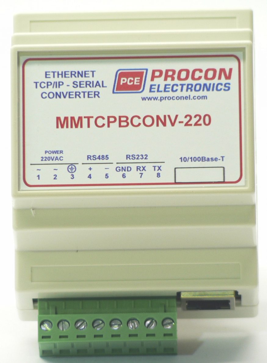
MMTCPBCONV – TCP / RS232(RS485) Ethernet/Serial Converter

The Ethernet/Serial Boxed Converter enables serial devices, such as PROMUX modules, communicating on RS232/485 to be connected to a 10/100 Base-TX Ethernet network.

The Ethernet/Serial Converter can be configured to operate in a number of different modes depending on the application. It can be configured as a transparent data link or it can perform the gateway function of converting Modbus TCP messages to Modbus RTU messages.

Mode 0: Server with slave device connected to the serial port, multi socket.
Mode 1: Server with slave device connected to the serial port or to be used with a Client Converter for point-to-point, single socket.
Mode 2: Client to be used with a Server Converter for point-to-point, single socket.

The Ethernet/Serial Converter includes a web server which enables access to internal parameters for configuration. This allows configuration of IP address, serial data format and operating modes. The web server can be accessed by most web browsers.

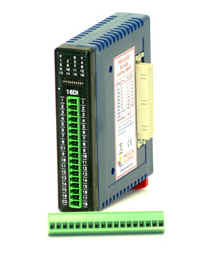
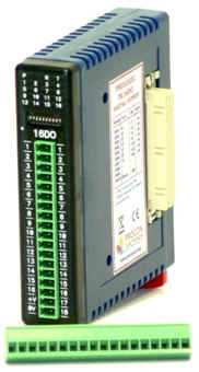
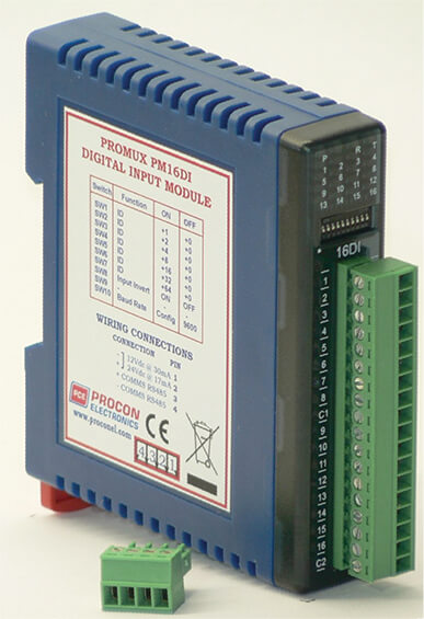
PM16DI – 16 Digital Input Module

PROMUX is an innovative modular I/O system which provides a simple low cost solution for distributed I/O requirements.

The PROMUX system consists of stand-alone Digital and Analog Input and Output modules which are connected together on a RS485 two wire multi-drop network. The modules communicate using the MODBUS RTU protocol.

A 32bit ARM CPU is used in the modules to provide high speed data processing and fast communications turn around times. Multiple baud rates are selectable from 2400 to 115200 baud.

All PROMUX modules plug directly onto an industry standard DIN rail. All modules have a minimum isolation of 1000VAC rms between the field and logic. The modules have been equipped with status led’s which are used to indicate the status of the Inputs or outputs. This visual indication assists with fault finding and diagnostics.

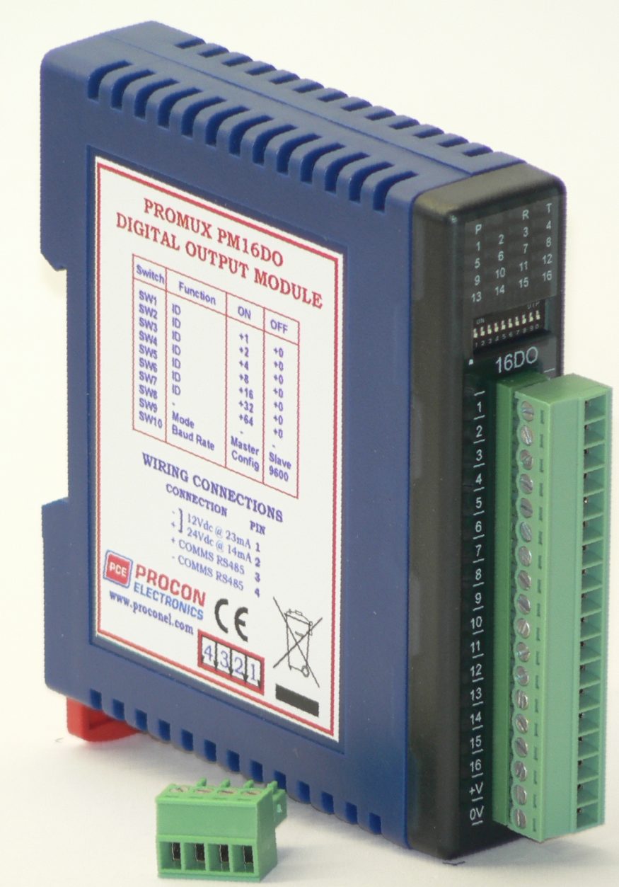
PM16DO – 16 DIGITAL OUTPUT MODULE

This module has 16 open collector (NPN) digital outputs. The outputs may be used to drive lamps or external relays when more drive capability is required. The outputs are isolated from the logic and they share a common negative terminal.

Each output can be individually switched on or off, or all outputs can be set up at the same time by writing a single number to the output register which represents the status of all outputs.

The module may be used as either a slave or master on the Modbus network. When used with a PC or PLC the module will be configured as a slave. When used with a PM16DI module in a point-to-point configuration, the DIP switch 9 must be turned on to set the module up as a master. In this mode the PM16DO module will automatically read the information from the PM16DI module and write the input status to the outputs.

An output watchdog timer can be configured to switch off all the outputs if there has been no communications with the module for up to 255 seconds. A value of 0 seconds will disable this timer and the outputs will remain in the last programmed state.
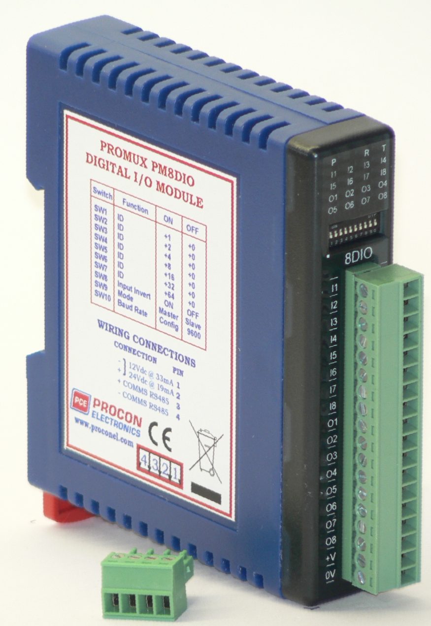
PM8DIO – 8 Digital Input/ Output Module

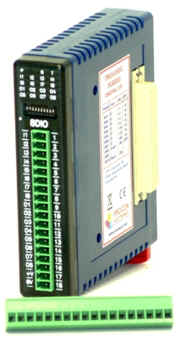
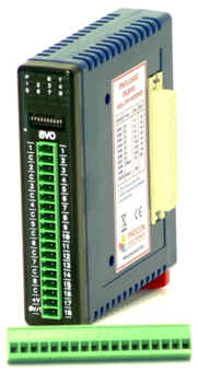
The PM8DIO module is an 8 channel digital input and 8 channel digital output module.

The inputs are isolated from the logic by bi-directional opto-couplers. The common is connected internally to either the -volts or +volts field power supply terminals using a jumper link which is situated inside the housing.

The module may be used as either a slave or master on the Modbus network. When used with a PC or PLC the module will be configured as a slave. When used with another PM8DIO module in a point-to-point configuration, the DIP switch 9 must be turned on to set the module up as a master. In this mode the PM8DIO module will automatically read/write the information from/to the other PM8DIO module.

The inputs have internal counters associated with them. These counters are 32 bit counters allowing a count value from 0 to 4294967295. The count value can be cleared by writing a zero to the associated registers or preset to any other value using the same method. The counters can also be reset automatically when read. This is done by setting on DIP switch 9 on the front panel.

Note: The count values are not battery backed-up and will be lost if power is turned off.

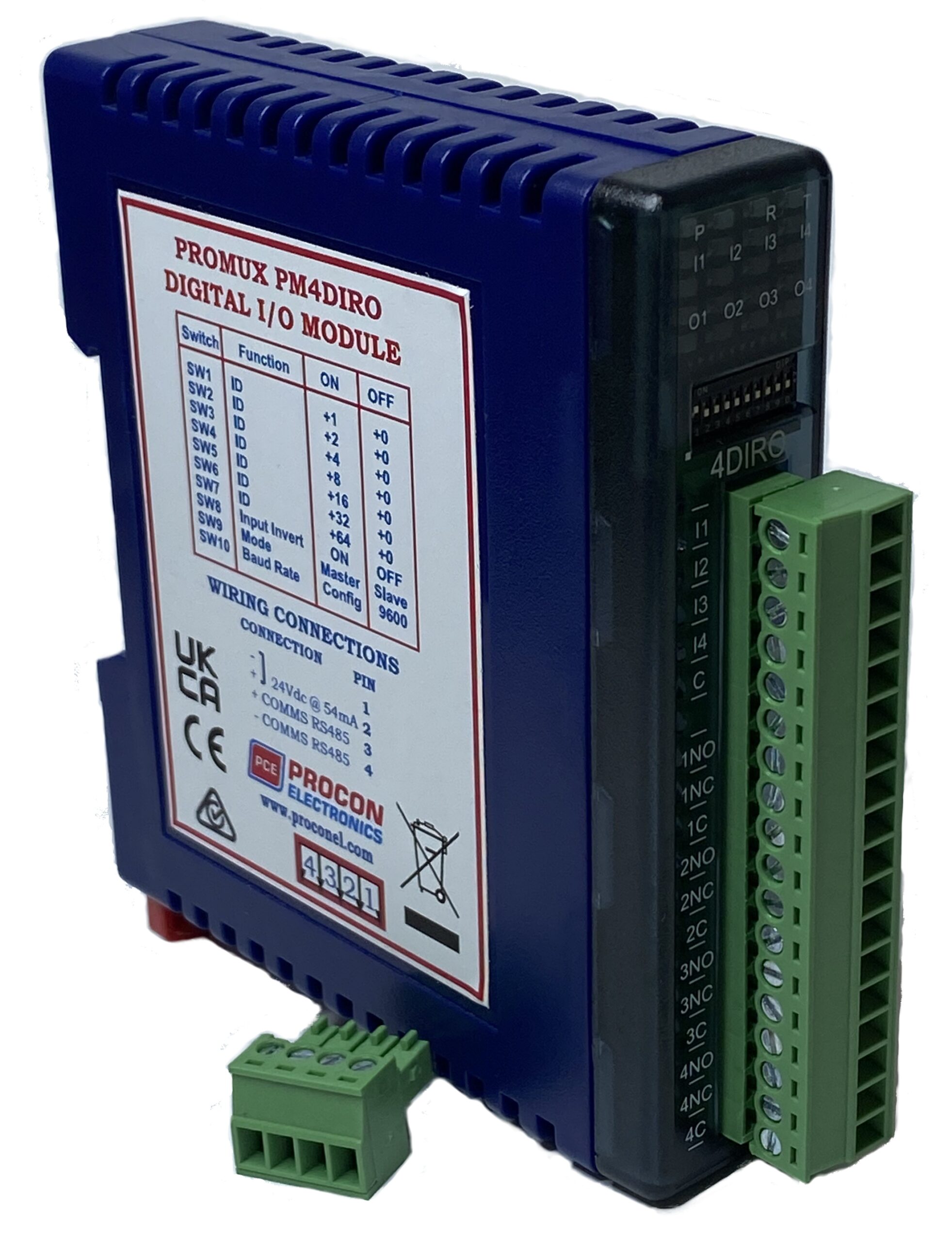
PM4DIRO – 4 Digital Input/ Relay Output Module

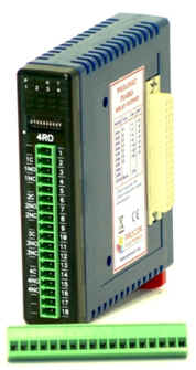
The PM4DIRO module is an 4 channel digital input and 4 channel relay output module.

The inputs are isolated from the logic by bi-directional opto-couplers. The common can be connected to either the -volts or +volts field power supply terminals.

The inputs have internal counters associated with them. These counters are 32 bit counters allowing a count value from 0 to 4294967295. The count value can be cleared by writing a zero to the associated registers or preset to any other value using the same method.

Note: The count values are not battery backed-up and will be lost if power is turned off.

The format of the registers allows the status of the inputs to be read as either single bits or all at once as a single register on the Modbus network.

The 4 relay outputs provide normally open and normally closed contacts. The outputs may be used to drive lamps or external relays when more drive capability is required. The outputs are isolated from the logic.

The module may be used as either a slave or master on the Modbus network. When used with a PC or PLC the module will be configured as a slave. When used with another PM4DIRO module in a point-to-point configuration, the DIP switch 9 must be turned on to set the module up as a master. In this mode the PM4DIRO module will automatically read/write the information from/to the other PM4DIRO module.

When used as a slave module, the outputs are written to by the Modbus master device such as a PC or PLC. Each output can be individually switched on or off, or all outputs can be set up at the same time by writing a single number to the output register which represents the status of all outputs.

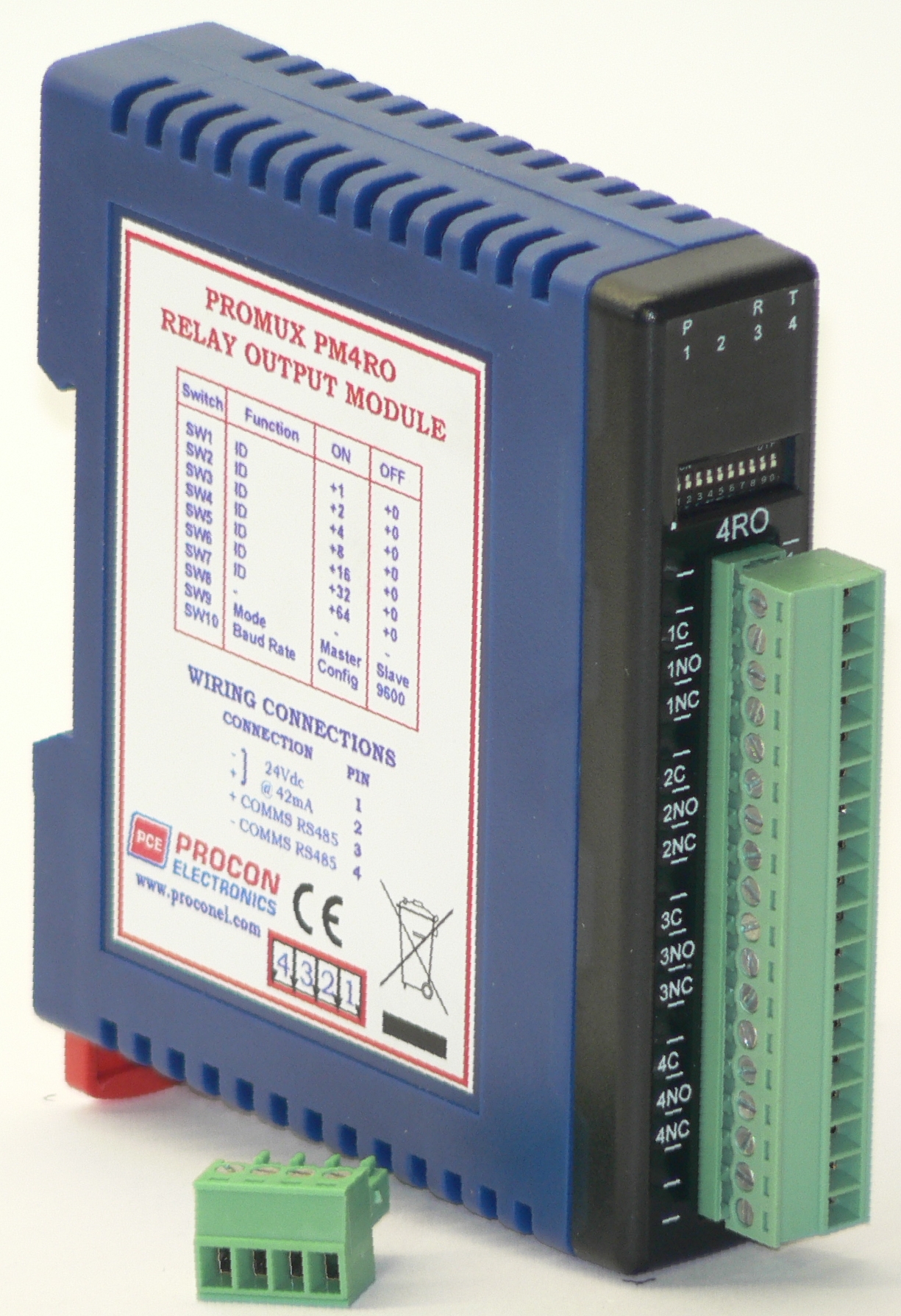
PM4RO – 4 Relay Output Module

The PM4RO module has 4 normally open/ normally closed relay outputs. These modules may be used when a higher drive capability is required, or when isolation between outputs are required.

Each output can be individually switched on or off, or all outputs can be set up at the same time by writing a single number to the output register which represents the status of all outputs.

The module may be used as either a slave or master on the Modbus network. When used with a PC or PLC the module will be configured as a slave. When used with a PM16DI module in a point-to-point configuration, the DIP switch 9 must be turned on to set the module up as a master. In this mode the PM4RO module will automatically read the information from the PM16DI module and write the input status to the outputs.

An output watchdog timer can be configured to switch off all the outputs if there has been no communications with the module for up to 255 seconds. A value of 0 seconds will disable this timer and the outputs will remain in the last programmed state.
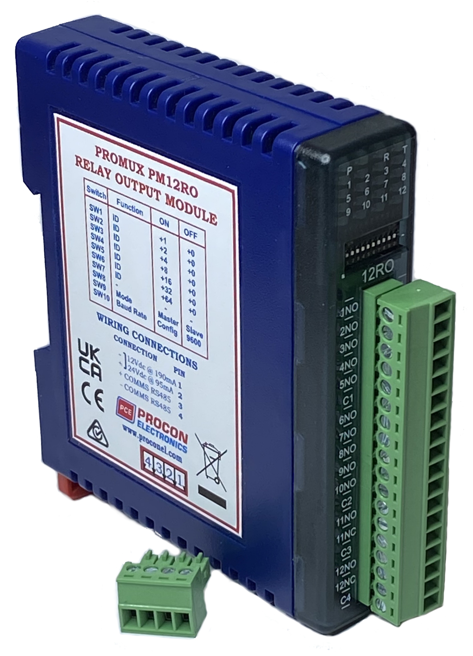
PM12RO – 12 Relay Output Module

The PM12RO module has 12 relay outputs. These modules may be used when a higher drive capability is required, or when isolation between outputs are required.

The module may be used as either a slave or master on the Modbus network. When used with a PC or PLC the module will be configured as a slave. When used with a PM16DI module in a point-to-point configuration, the DIP switch 9 must be turned on to set the module up as a master. In this mode the PM12RO module will automatically read the information from the PM16DI module and write the input status to the outputs.

When used as a slave module, the outputs are written to by the Modbus master device such as a PC or PLC. Each output can be individually switched on or off, or all outputs can be set up at the same time by writing a single number to the output register which represents the status of all outputs.

An output watchdog timer can be configured to switch off all the outputs if there has been no communications with the module for up to 255 seconds. A value of 0 seconds will disable this timer and the outputs will remain in the last programmed state.
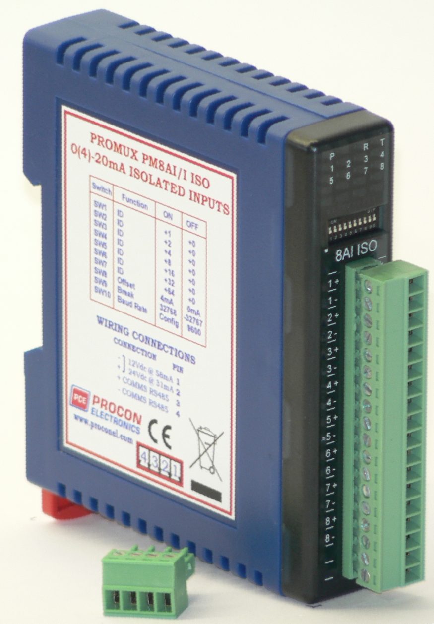
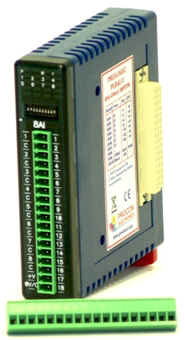
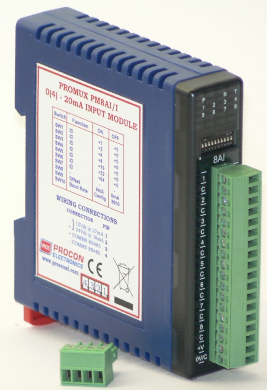
PM8AI/I – 8 Current Input Module

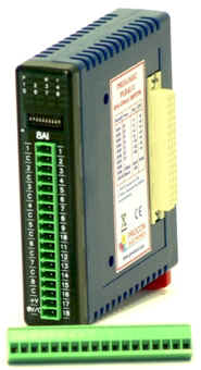
The PM8AI/I is a 8 channel current input module. The inputs are isolated from the logic and share a common negative terminal.

The standard setting for the PM8AI/I module is 0 – 20mA input current which represents an output value of 0 – 4095 (12 bits) in the corresponding Modbus register. To obtain an output value of 0 to 4095 for an input signal of 4 to 20mA the offset switch is switched on.

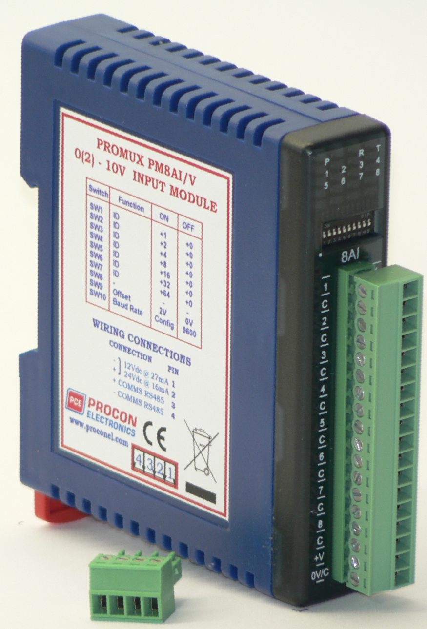
PM8AI/V – 8 Voltage Input Module

The PM8AI/V is a 8 channel voltage input module. The inputs are isolated from the logic and share a common negative terminal.

The standard setting for the PM8AI/V module is 0 – 10V. An input voltage of 0 – 10Volts represents an output of 0 – 4095 and 2 volts would give a reading of 819 ± 1LSB. To obtain an output value of 0 to 4095 for an input signal of 2 to 10V the offset switch is switched on. An input range of 0(1) to 5Vdc is available by removing the jumper link located on the analogue board inside the enclosure.

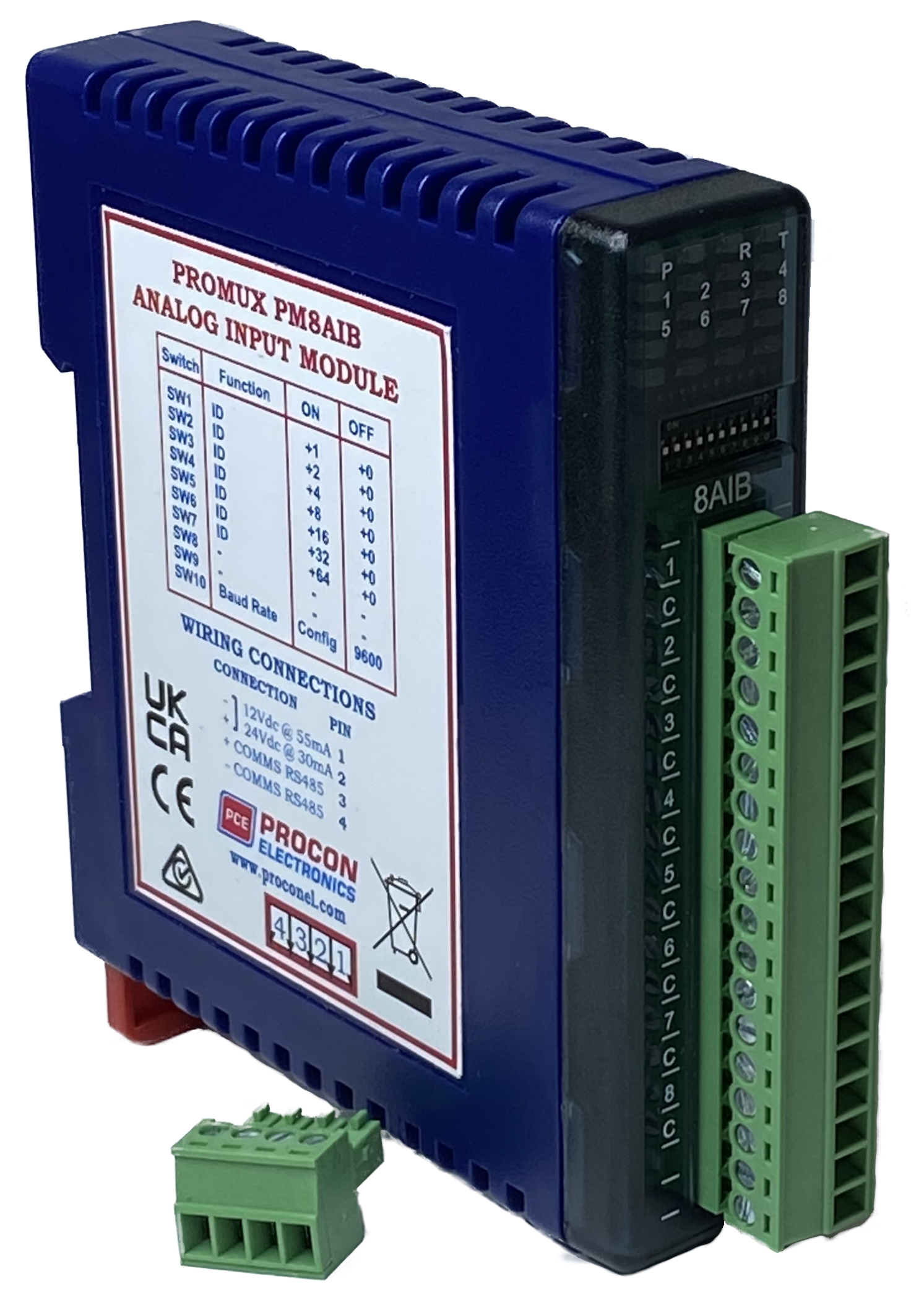
PM8AIB – Analog Input Module

The PM8AIB module is a fast voltage or current input module with 16bits resolution. The Analog Inputs can be configured as either a current input or a voltage input using DIP switches. The inputs are isolated from the logic and share a common negative terminal.

The PM8AIB can be configured for 0-10V, +/-10V or +/-5V input measurement or 0-20mA, 4-20mA or +/-20mA measurement.

The module can also be configured to display in 16bit binary format (0 to 65535 or -32768 to 32767) or engineering units, for example (+/-10.000 volts or 0 to 20.000mA)

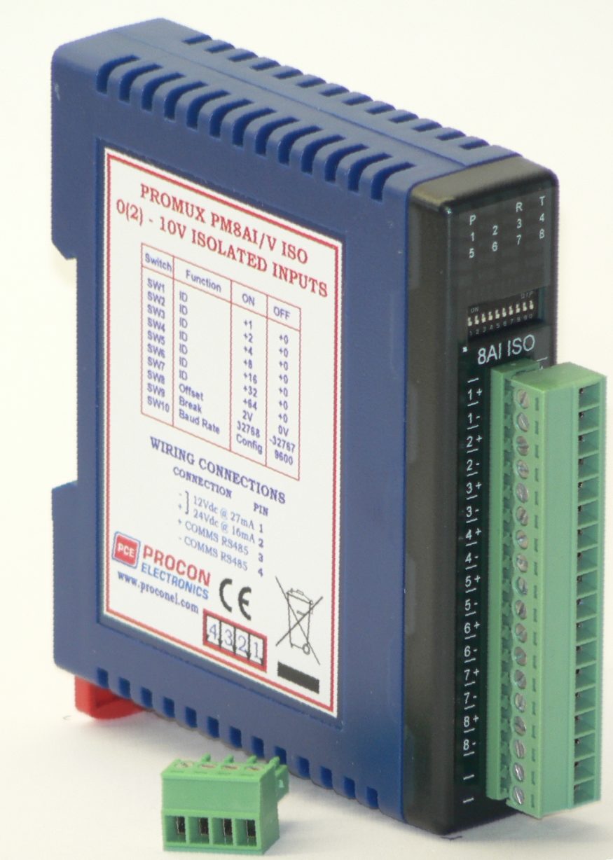
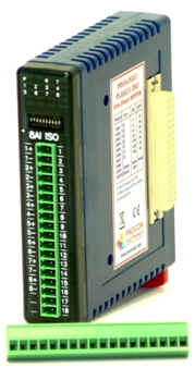
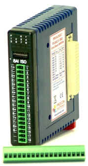
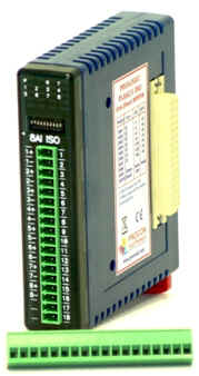
PM8AI/V ISO – 8 Voltage Input Module Fully Isolated

The PM8AI/V ISO is a 8 channel voltage input module. The inputs are fully isolated from input to logic and between inputs. This module is ideal for monitoring voltages which are isolated from each other and cannot be connected to a common point of reference.

The standard setting for the PM8AI/V module is 0 – 10V. An input voltage of 0 – 10Volts represents an output of 0 – 4095 and 2 volts would give a reading of 819 ± 1LSB. To obtain an output value of 0 to 4095 for an input signal of 2 to 10V the offset switch is switched on. The module can also be configured for 16 bit (0 – 65535). This module can also be configured for a 0 – 10.000V input range or +/- 10.000V input.

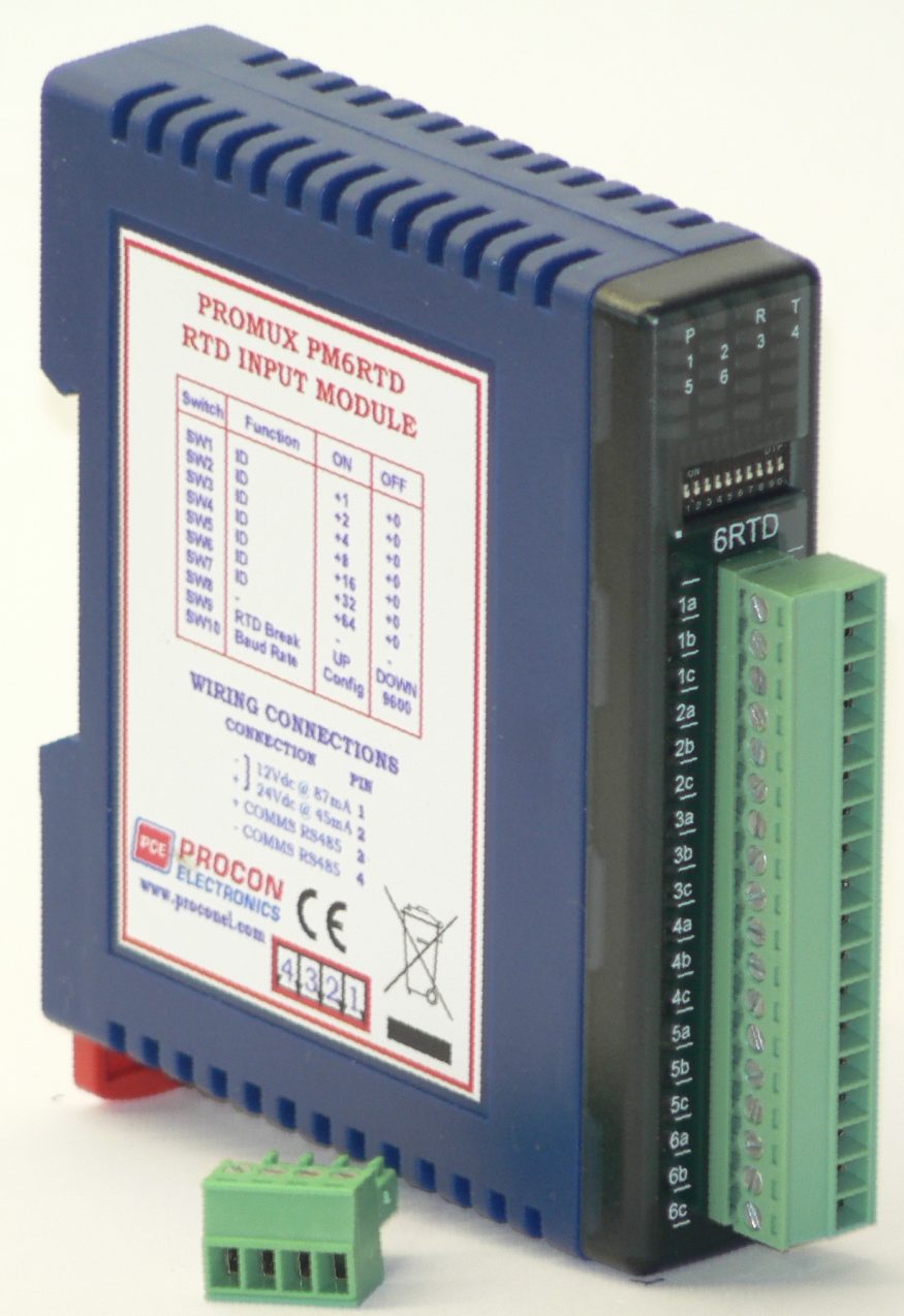
PM6RTD – 6 RTD Input Module

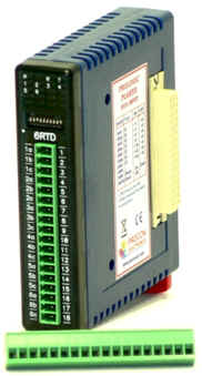
The PM6RTD module is a 6 RTD input module. The module can accommodate either 2 or 3 wire RTD sensors. The RTD inputs are isolated from the logic.

The RTD resistance is read by the module circuitry, linearised and converted to degrees Centigrade. No ranging is required as the module covers the full range of the RTD as indicated in the RTD table. The value that is read from the Modbus register is the actual temperature in degrees centigrade to 0.1°C resolution. ie: a value of 3451 corresponds to a temperature of 345.1°C.

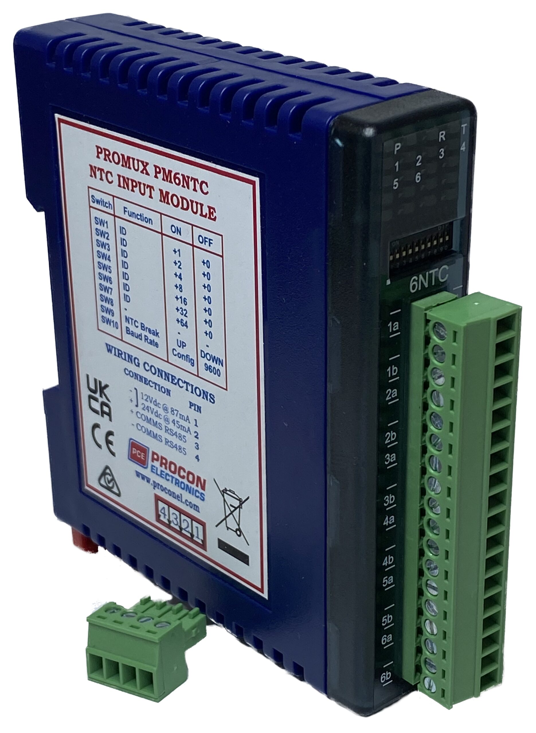
PM6NTC – NTC INPUT MODULE

The PM6NTC module is a 6 NTC input module. The module uses 2 wire NTC sensors. The NTC inputs are isolated from the logic.

The NTC resistance is read by the module circuitry, linearized and converted to degrees Centigrade or Fahrenheit. No ranging is required as the module covers the full range of the NTC as indicated in the NTC table. The value that is read from the Modbus register is the actual temperature in degrees to 0.1°C resolution. ie: a value of 3451 corresponds to a temperature of 345.1°C.

The NTC type is setup by writing a value to the NTC Type register. The value is obtained from the table below. For example to select a 10K NTC, the value “1” must be written to the NTC Type register. All 6 NTC inputs adopt the same NTC type.

The DIP switch 9 is used to select upscale or downscale burnout for break detection. A value of 32768 is used to indicate upscale burnout and a value of -32767 is used to indicate downscale burnout.

Note: As there is no inter-channel isolation, isolated NTC’s must be used in order to prevent ground loops and reading errors.

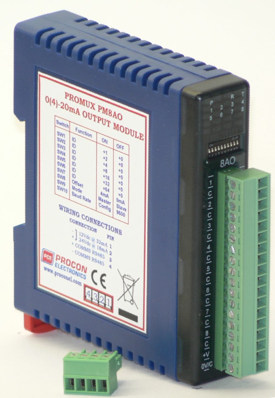
PM8AO – 8 Current Output Module

The PM8AO is a 8 channel current output module. Each channel can be set to output a current in the range 0 – 20mA. The outputs are isolated from the logic and share a common negative terminal.

The resolution is 12 bits, so writing a value to the Modbus register for each output of 0 – 4095 would give an output current of 0 – 20mA. A value of 819 ± 1LSB will give a current output of 4mA.

The module may be used as either a slave or master on the Modbus network. When used with a PC or PLC the module will be configured as a slave. When used with a PM8AI module in a point-to-point configuration, the DIP switch 9 must be turned on to set the module up as a master. In this mode the PM8AO module will automatically read the information from the PM8AI module and write the input status to the outputs.

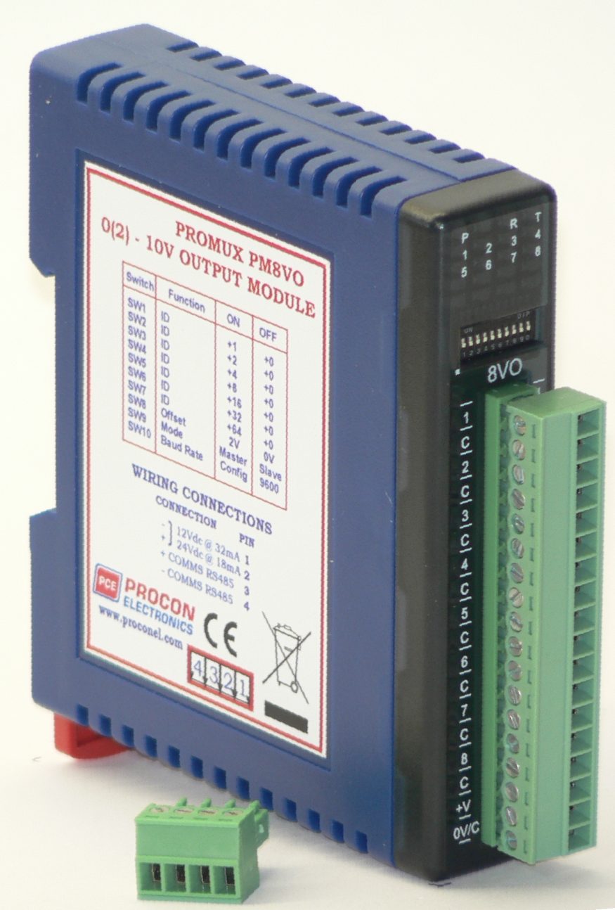
PM8VO – 8 Voltage Output Module

The PM8VO is a 8 channel voltage output module. Each channel can be set to output a voltage in the range 0 – 10V. The outputs are isolated from the logic and share a common negative terminal.

The resolution is 12 bits, so writing a value to the Modbus register for each output of 0 – 4095 would give an output current of 0 – 10V. A value of 819 ± 1LSB will give a current output of 2V.

The module may be used as either a slave or master on the Modbus network. When used with a PC or PLC the module will be configured as a slave. When used with a PM8AI module in a point-to-point configuration, the DIP switch 9 must be turned on to set the module up as a master. In this mode the PM8VO module will automatically read the information from the PM8AI module and write the input status to the outputs.

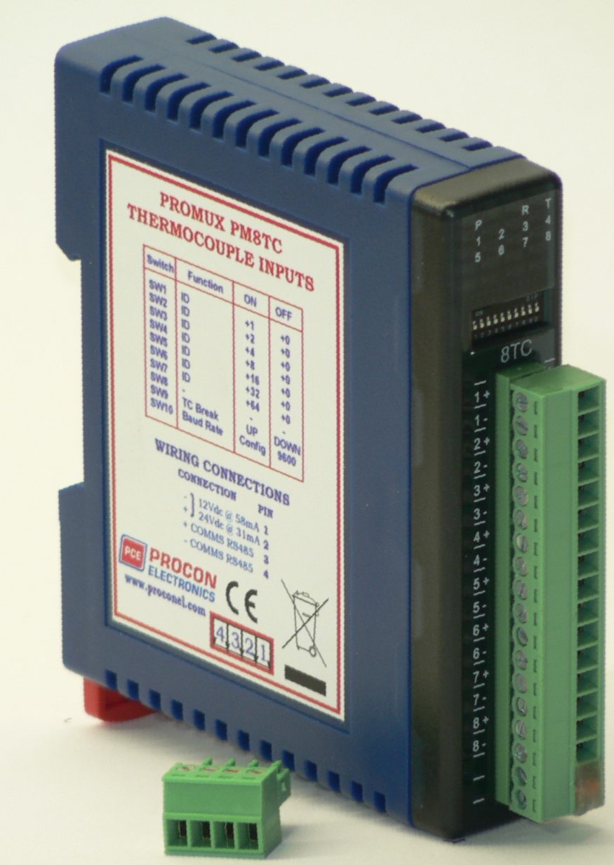
PM8TC – 8 Thermocouple Input Module

The PM8TC module is a 8 thermocouple input module. The module uses differential inputs to reduce effects of electrical noise and mains pickup. The thermocouple inputs are isolated from the logic. If inter channel isolation is required then the PM8TCISO should be used.

The thermocouple voltage is read by the module circuitry, linearised and converted to degrees Centigrade. No ranging is required as the module covers the full range as indicated in the table of TC types. The value that is read from the Modbus register is the actual temperature in degrees centigrade to 0.1°C resolution. ie: a value of 3451 corresponds to a temperature of 345.1°C.

The module has built in Cold Junction Compensation. Use must be made of the correct thermocouple extension wire to avoid reading errors.

The thermocouple module can also be configured for a 0 – 50mV input range. The TC Type register must be set to 9 for this option. The value in the register which is read back over the network is 0 – 50,000.

Note: As there is no inter-channel isolation, isolated thermocouples must be used in order to prevent ground loops and reading errors.

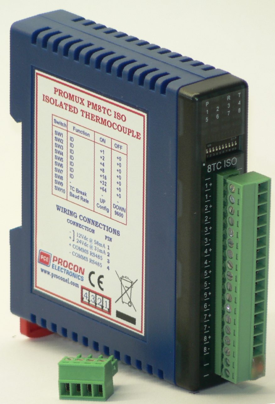
PM8TC ISO – 8 Thermocouple Input Module Isolated

The PM8TCISO module is a 8 isolated thermocouple input module. The module uses differential inputs to reduce effects of electrical noise and mains pickup. The thermocouple inputs are isolated from the logic and from each other. This module is operated in an identical way to the PM8TC module and is fully interchangeable.

The thermocouple voltage is read by the module circuitry, linearised and converted to degrees Centigrade. No ranging is required as the module covers the full range as indicated in the TC table. The value that is read from the Modbus register is the actual temperature in degrees centigrade to 0.1°C resolution. ie: a value of 3451 corresponds to a temperature of 345.1°C.

The module has built in Cold Junction Compensation. Use must be made of the correct thermocouple extension wire to avoid reading errors.

The thermocouple module can also be configured for a 0 – 50mV input range. The TC Type register must be set to 9 for this option. The value in the register which is read back over the network is 0 – 50,000.

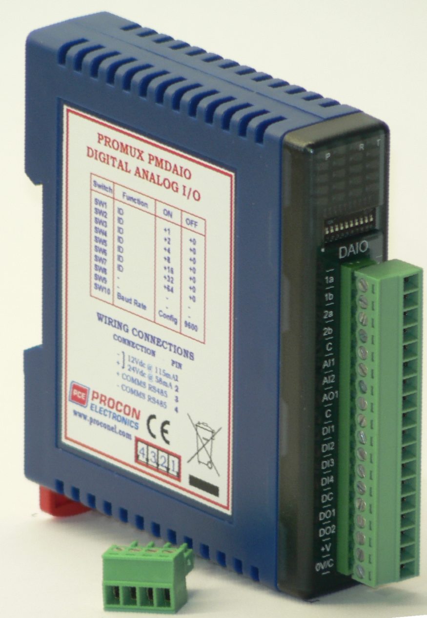
PMDAIO – Universal I/O – 2 RTD , 2 AI, 1 AO, 4 DI, 2 DO

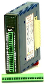
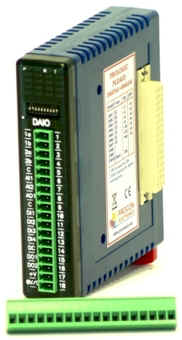
The PMDAIO module is a multipurpose combination of inputs and outputs. The module can accommodate either 2 or 3 wire RTD sensors, current (0-20mA) and voltage (0-10V) inputs, current (0-20mA) or voltage (0-10V) output, and digital inputs and outputs.

RTD INPUTS:
There are 2 RTD inputs on the module. The RTD resistance is read by the module circuitry, linearised and converted to degrees Centigrade. No ranging is required as the module covers the full range of the RTD as indicated in the RTD table. The value that is read from the Modbus register is the actual temperature in degrees centigrade to 0.1°C resolution. ie: a value of 3451 corresponds to a temperature of 345.1°C.

ANALOG INPUTS:
The Analog Inputs (2) can be configured by internal jumpers as either a current input (0-20mA) or a voltage input (0-10V).

An input of 0 – 20mA input current or 0 – 10V input voltage represents an output value of 0 – 4095 (12 bits) in the corresponding Modbus register.

ANALOG OUTPUT:
There is a single analog output which can be configured with internal jumpers for a current output (0-20mA) or voltage output (0-10V).

The resolution is 12 bits, so writing a value to the Modbus register for each output of 0 – 4095 would give an output current of 0 – 20mA. A value of 819 ± 1LSB will give a current output of 4mA.

DIGITAL INPUTS:
There are 4 digital inputs on the module. The inputs share a common terminal and can be configured for common positive or common negative.

The inputs have got counters associated with them. The counters operate in three modes.

In mode 0 all the counters are disabled.

In mode 1 all counters are 32 bit counters allowing a count value from 0 to 4294967295. The count value can be cleared by writing a zero to the associated registers or preset to any other value using the same method.

In mode 2 the inputs are connected as up/down counters. Input 1 will increment counter 1 whilst input 2 decrements counter1.

Note: The count values are not battery backed-up and will be lost if power is turned off.

The format of the registers allows the status of the inputs to be read as either single bits or all at once as a single register on the Modbus network.

DIGITAL OUTPUTS:
The module has 2 open collector (NPN) digital outputs. The outputs may be used to drive lamps or external relays when more drive capability is required.

The outputs are written to by the Modbus master device such as a PC or PLC. Each output can be individually switched on or off, or all outputs can be set up at the same time by writing a single number to the output register which represents the status of all outputs.

An output watchdog timer can be configured to switch off all the outputs if there has been no communications with the module for up to 255 seconds. A value of 0 seconds will disable this timer and the outputs will remain in the last programmed state.
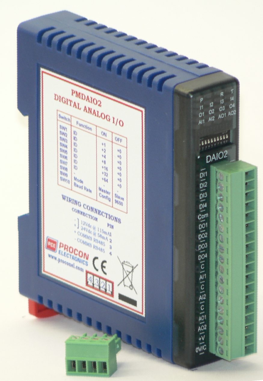
PMDAIO2 – Universal I/O – 2 AI, 2 AO, 4 DI, 4 DO

The PMDAIO2 module is a multipurpose combination of inputs and outputs. The module can accommodate either current (0-20mA) or voltage (0-10V) inputs, current (0-20mA) outputs, and digital inputs and outputs.

ANALOG INPUTS:
The Analog Inputs (2) can be configured by internal jumpers as either a current input (0-20mA) or a voltage input (0-10V).

An input of 0 – 20mA input current or 0 – 10V input voltage represents an output value of 0 – 4095 (12 bits) in the corresponding Modbus register.

ANALOG OUTPUTS:
The analog outputs are current outputs (0-20mA)

The resolution is 12 bits, so writing a value to the Modbus register for each output of 0 – 4095 would give an output current of 0 – 20mA. A value of 819 ± 1LSB will give a current output of 4mA.

DIGITAL INPUTS:
There are 4 digital inputs on the module. The inputs share a common terminal and can be configured for common positive or common negative. The inputs have got counters associated with them. The counters operate in three modes.

In mode 0 all the counters are disabled.
In mode 1 all counters are 32 bit counters allowing a count value from 0 to 4294967295. The count value can be cleared by writing a zero to the associated registers or preset to any other value using the same method.
In mode 2 the inputs are connected as up/down counters. Input 1 will increment counter 1 whilst input 2 decrements counter1.

Note: The count values are not battery backed-up and will be lost if power is turned off.

The format of the registers allows the status of the inputs to be read as either single bits or all at once as a single register on the Modbus network.

DIGITAL OUTPUTS:
The module has 4 open collector (NPN) digital outputs. The outputs may be used to drive lamps or external relays when more drive capability is required.

The outputs are written to by the Modbus master device such as a PC or PLC. Each output can be individually switched on or off, or all outputs can be set up at the same time by writing a single number to the output register which represents the status of all outputs.

An output watchdog timer can be configured to switch off all the outputs if there has been no communications with the module for up to 255 seconds. A value of 0 seconds will disable this timer and the outputs will remain in the last programmed state.
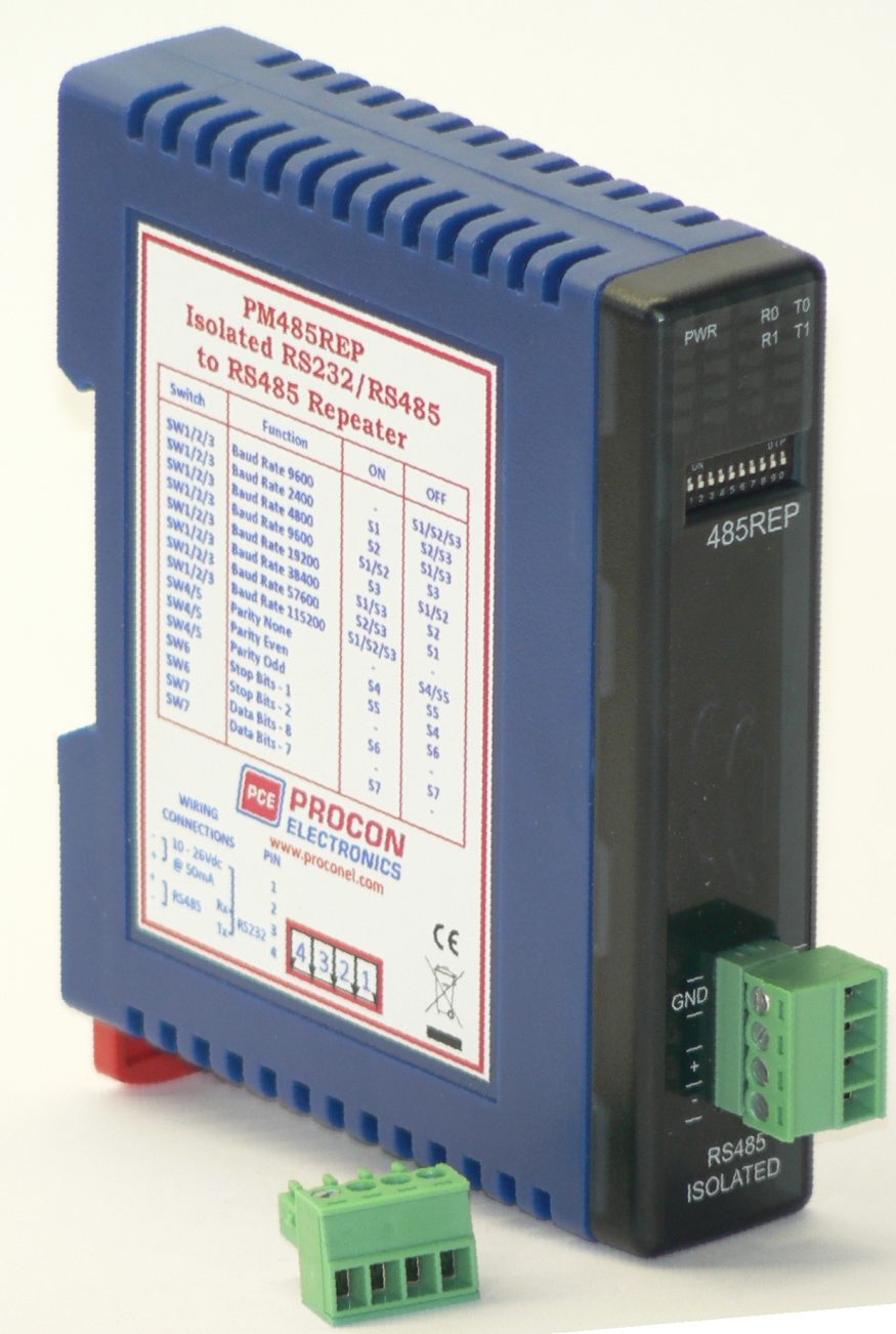
PM485REP – RS232/RS485 to RS485 Isolated Repeater

The PM485REP unit is a bi-direction isolated serial repeater unit used to convert 2 wire RS485 twisted pair (or 3 wire RS232) data communications signals to another isolated 2 wire RS485 twisted pair cable. The unit is fully configurable via DIP switches for baud rate, parity, data bits and stop bits. The repeater can be used to extend a RS485 network up to a further 1000 metres. The isolation also prevents ground loops between different parts of the network.

The PM485REP is the ideal unit to use for isolating Promux modules housed in an electrical panel from long RS485 networks which could suffer from ground loop problems.

The PM485REP can also be used as a RS232 to RS485 isolated converter.

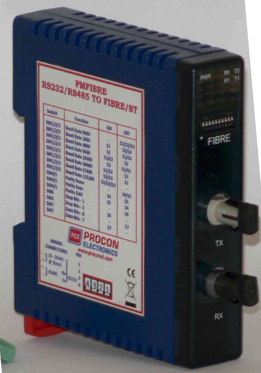
PM485FIBRE – RS232/RS485 to Fibre Module

The PMFibre Optic converter unit is a bi-direction fibre optic unit used to convert 2-wire RS485 twisted pair (or 3 wire RS232) data communications signals for transmission over multi-mode fibre optic cables.

The converters can be used to extend the limited distance capabilities of RS485 devices for up to two kilometres. The PMFibre Optic converter is ideal for extending RS485 signals through areas of high electrical noise due to the EMI immunity of fibre. 

The unit is also ideal for isolating Promux modules housed in an electrical panel from long RS485 networks which could suffer from ground loop problems. 

The unit is fully configurable via DIP switches for baud rate, parity, data bits and stop bits. The isolation also prevents ground loops between different parts of the network.

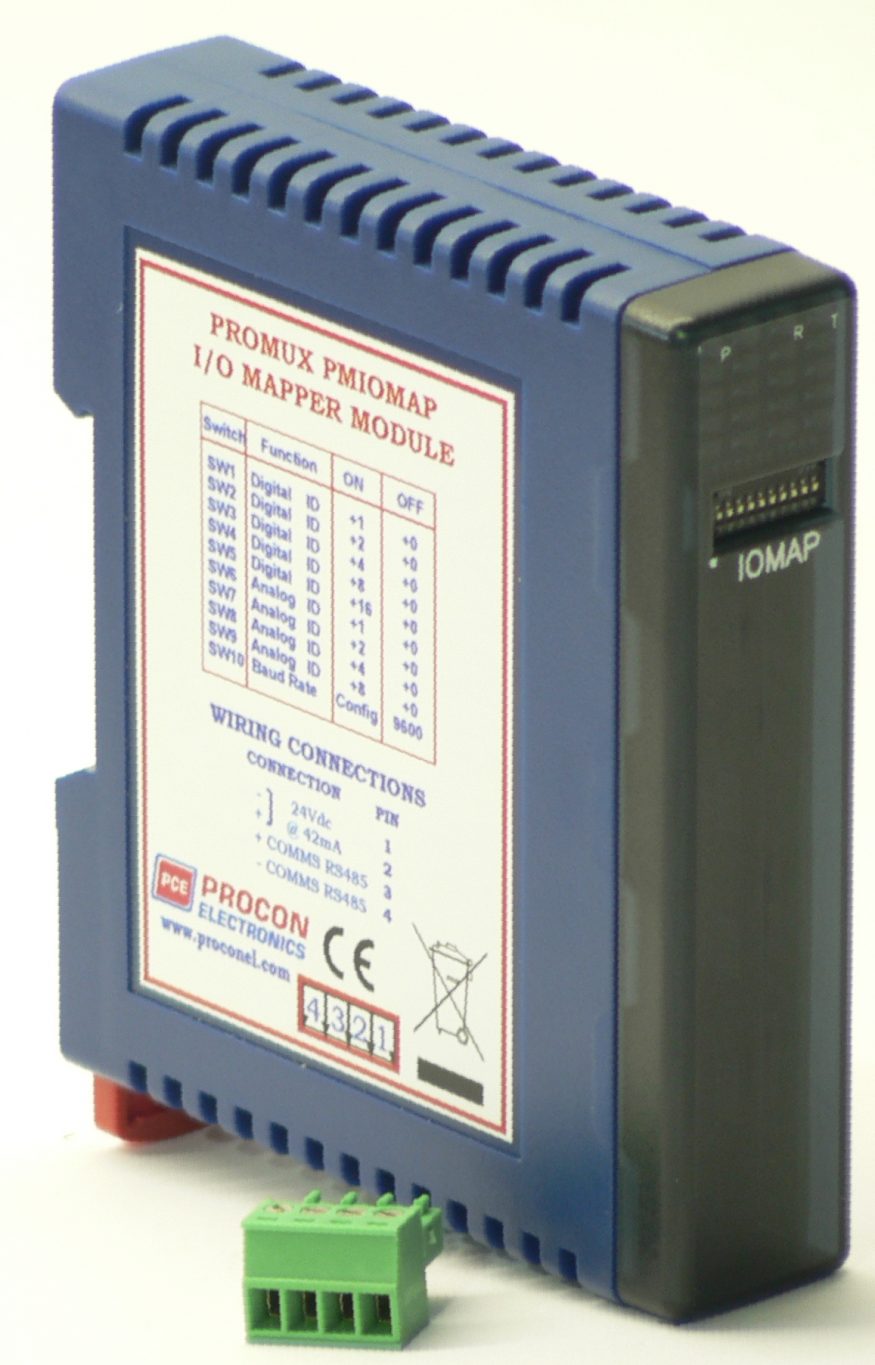
PMIOMAPTYPE2 – I/O Mapper Module Type 2

The I/O Mapper is used for point-to-point communications where it is required to send information from a PM16DI to PM16DO, PM8AI to a PM8AO, between 2 PM8DIO modules, between 2 PMDAIO modules or between 2 PMDAIO2 modules over the network. The I/O Mapper is the Modbus master and all I/O modules must be set up as slaves.

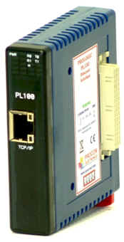
PL100 – Ethernet Interface Module

The PL100 is an Ethernet to serial converter and connects the PROLOGIC modules to a 10/100 Base-TX Ethernet network.

The PL100 includes a web server which enables access to internal parameters for configuration. This allows configuration of IP address, default gateway IP address and subnet mask. The web server can be accessed by most web browsers.

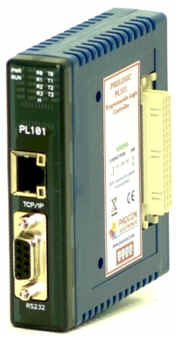
PL101 – Programmable Logic Controller Module

The PL101 PLC has been developed as a compact controller with a versatile combination of communication ports. The fact that the controller is programmable enables the user to program their own unique logic requirements and not be restricted by a pre-programmed unit or hardwired relays and timers.

The PROLOGIC modules plug into each other and the module on the left plugs into the PL101. Up to eight modules can plugged together.

The PL101 PLC is programmed in ladder logic. Procon’s ProSoft windows-based PC software is used to generate the ladder diagram, compile the program, and then download the program to the PL101 via the Ethernet port on the front of the unit.

The PL101 includes a web server which enables access to internal parameters for configuration. This allows configuration of IP address, default gateway IP address and subnet mask. The web server can be accessed by most web browsers. The PL101 supports the FTP protocol which enables the web pages to be customized if required.

PL16DI – 16 Digital Input Module

The PL16DI module is a 16 channel digital input module. The inputs are isolated from the logic by bi-directional opto-couplers. The inputs are divided into 2 isolated groups of 8 inputs each. This allows for many configurations in which the input module may be used. One such configuration could be where one group is connected as common positive and the second group connected as common negative.

The counters operate in three modes.

In mode 0: All the counters are disabled.

In mode 1: The counters are 32 bit counters allowing a count value from 0 to 4294967295. The count value can be cleared by writing a zero to the associated registers or preset to any other value using the same method.

In mode 2: The inputs are connected as up/down counters. Input 1 will increment counter 1 whilst input 2 decrements counter1. In the same way, inputs 3&4 operate counter 2, inputs 5&6 operate counter 3 and inputs 7&8 operate counter 4,etc.

When the input filter is configured for > 10ms (Input Filter > 1), then the 16 counters are saved in non-volatile memory and the count value will be saved when the power fails.

PL16DO – 16 Digital Output Module

This module has 16 open collector (NPN) digital outputs. The outputs may be used to drive lamps or external relays when more drive capability is required. The outputs are isolated from the logic and they share a common negative terminal.

Each output can be individually switched on or off, or all outputs can be set up at the same time by writing a single number to the output register which represents the status of all outputs.

An output watchdog timer can be configured to switch off all the outputs if there has been no communications with the module for up to 255 seconds. A value of 0 seconds will disable this timer and the outputs will remain in the last programmed state.
PL8DIO – 8 Digital Input/Output Module

The PL8DIO module is an 8 channel digital input and 8 channel digital output module.

The inputs are isolated from the logic by bi-directional opto-couplers. The common is connected internally to either the -volts or +volts field power supply terminals using a jumper link which is situated inside the housing.

The inputs have internal counters associated with them. These counters are 32 bit counters allowing a count value from 0 to 4294967295.

PL4RO – 4 Relay Output Module

The PL4RO module has 4 normally open/ normally closed relay outputs. These modules may be used when a higher drive capability is required, or when isolation between outputs are required.

An output watchdog timer can be configured to switch off all the outputs if there has been no communications with the module for up to 255 seconds. A value of 0 seconds will disable this timer and the outputs will remain in the last programmed state.
PL8AI/I – 8 Current Input Module

The PL8AI/I is a 8 channel current input module. The inputs are isolated from the logic and share a common negative terminal.

The standard setting for the PL8AI/I module is 0 – 20mA input current which represents an output value of 0 – 4095 (12 bits) in the corresponding Modbus register. To obtain an output value of 0 to 4095 for an input signal of 4 to 20mA the offset switch is switched on.

PL8AI/I ISO – 8 Current Input Module Fully Isolated

The PL8AI/I ISO is a 8 channel current input module. The inputs are fully isolated from input to logic and between inputs. This module is ideal for monitoring existing 4-20mA current loops which are isolated from each other and cannot be connected to a common point of reference.

The standard setting for the PL8AI/I module is 0 – 20mA input current which represents an output value of 0 – 4095 (12 bits) or 0-65535(16 bits) in the corresponding Modbus register. To obtain an output value of 0 to 4095 for an input signal of 4 to 20mA the offset switch is switched on. This module can also be configured for a 0 – 20.000mA input range or +/- 20.000mA input.

PL8AI/V – 8 Voltage Input Module

The PL8AI/V is a 8 channel voltage input module. The inputs are isolated from the logic and share a common negative terminal.

The standard setting for the PL8AI/V module is 0 – 10V. An input voltage of 0 – 10Volts represents an output of 0 – 4095 and 2 volts would give a reading of 819 ± 1LSB.  To obtain an output value of 0 to 4095 for an input signal of 2 to 10V  the offset switch is switched on. An input range of 0(1) to 5Vdc is available by removing the jumper link located on the analogue board inside the enclosure.

PL8AI/V ISO – 8 Voltage Input Module Fully Isolated

The PL8AI/V ISO is a 8 channel voltage input module. The inputs are fully isolated from input to logic and between inputs. This module is ideal for monitoring voltages  which are isolated from each other and cannot be connected to a common point of reference.

The standard setting for the PL8AI/V module is 0 – 10V. An input voltage of 0 – 10Volts represents an output of 0 – 4095 and 2 volts would give a reading of 819 ± 1LSB.  To obtain an output value of 0 to 4095 for an input signal of 2 to 10V  the offset switch is switched on. The module can also be configured for 16 bit (0 – 65535). This module can also be configured for a 0 – 10.000V input range or +/- 10.000V input.

PL8AO – 8 Current Output Module

The PL8AO is a 8 channel current output module. Each channel can be set to output a current in the range 0 – 20mA. The outputs are isolated from the logic and share a common negative terminal.

The resolution is 12 bits, so writing a value to the Modbus register for each output  of 0 – 4095 would give an output current of 0 – 20mA. A value of 819 ± 1LSB will give a current output of 4mA.

PL8VO – 8 Voltage Output Module

The PL8VO is a 8 channel voltage output module. Each channel can be set to output a voltage in the range 0 – 10V. The outputs are isolated from the logic and share a common negative terminal.

The resolution is 12 bits, so writing a value to the Modbus register for each output  of 0 – 4095 would give an output current of 0 – 10V. A value of 819 ± 1LSB will give a current output of 2V.

PL8TC – 8 Thermocouple Input Module

The PL8TC module is a 8 thermocouple input module. The module uses differential inputs to reduce effects of electrical noise and mains pickup. The thermocouple inputs are isolated from the logic. If inter channel isolation is required then the PM8TCISO should be used.

The thermocouple voltage is read by the module circuitry, linearised and converted to degrees Centigrade. No ranging is required as the module covers the full range as indicated in the table of TC types. The value that is read from the Modbus register is the actual temperature in degrees centigrade to 0.1°C resolution. ie: a value of 3451 corresponds to a temperature of 345.1°C.

The module has built in Cold Junction Compensation. Use must be made of the correct thermocouple extension wire to avoid reading errors.

The thermocouple module can also be configured for a 0 – 50mV input range. The TC Type register must be set to 9 for this option. The value in the register which is read back over the network is 0 – 50,000.

Note: As there is no inter-channel isolation, isolated thermocouples must be used in order to prevent ground loops and reading errors.

PL8TC ISO – 8 Thermocouple Module Fully Isolated

The PL8TCISO module is a 8 isolated thermocouple input module. The module uses differential inputs to reduce effects of electrical noise and mains pickup. The thermocouple inputs are isolated from the logic and from each other. This module is operated in an identical way to the PM8TC module and is fully interchangeable.

The thermocouple voltage is read by the module circuitry, linearised and converted to degrees Centigrade. No ranging is required as the module covers the full range as indicated in the TC table. The value that is read from the Modbus register is the actual temperature in degrees centigrade to 0.1°C resolution. ie: a value of 3451 corresponds to a temperature of 345.1°C.

The module has built in Cold Junction Compensation. Use must be made of the correct thermocouple extension wire to avoid reading errors.

The thermocouple module can also be configured for a 0 – 50mV input range. The TC Type register must be set to 9 for this option. The value in the register which is read back over the network is 0 – 50,000.

PL6RTD – 6 RTD Input Module

The PL6RTD module is a 6 RTD input module. The module can accommodate either 2 or 3 wire RTD sensors. The RTD inputs are isolated from the logic.

The RTD resistance is read by the module circuitry, linearised and converted to degrees Centigrade. No ranging is required as the module covers the full range of the RTD as indicated in the RTD table.  The value that is read from the Modbus register is the actual temperature in degrees centigrade to 0.1°C resolution. ie: a value of 3451 corresponds to a temperature of 345.1°C.

PLDAIO – Universal I/O – 2 RTD , 2 AI, 1 AO, 4 DI, 2 DO

The PLDAIO module is a multipurpose combination of inputs and outputs. The module can accommodate either 2 or 3 wire RTD sensors, current (0-20mA) and voltage (0-10V) inputs, current (0-20mA) or voltage (0-10V) output, and digital inputs and outputs.

RTD INPUTS:
There are 2 RTD inputs on the module. The RTD resistance is read by the module circuitry, linearised and converted to degrees Centigrade. No ranging is required as the module covers the full range of the RTD as indicated in the RTD table. The value that is read from the Modbus register is the actual temperature in degrees centigrade to 0.1°C resolution. ie: a value of 3451 corresponds to a temperature of 345.1°C.

ANALOG INPUTS:
The Analog Inputs (2) can be configured by internal jumpers as either a current input (0-20mA) or a voltage input (0-10V).

An input of 0 – 20mA input current or 0 – 10V input voltage represents an output value of 0 – 4095 (12 bits) in the corresponding Modbus register.

ANALOG OUTPUT:
There is a single analog output which can be configured with internal jumpers for a current output (0-20mA) or voltage output (0-10V).

The resolution is 12 bits, so writing a value to the Modbus register for each output of 0 – 4095 would give an output current of 0 – 20mA. A value of 819 ± 1LSB will give a current output of 4mA.

DIGITAL INPUTS:
There are 4 digital inputs on the module. The inputs share a common terminal and can be configured for common positive or common negative.

The inputs have got counters associated with them. The counters operate in three modes.

In mode 0 all the counters are disabled.

In mode 1 all counters are 32 bit counters allowing a count value from 0 to 4294967295. The count value can be cleared by writing a zero to the associated registers or preset to any other value using the same method.

In mode 2 the inputs are connected as up/down counters. Input 1 will increment counter 1 whilst input 2 decrements counter1.

Note: The count values are not battery backed-up and will be lost if power is turned off.

The format of the registers allows the status of the inputs to be read as either single bits or all at once as a single register on the Modbus network.

DIGITAL OUTPUTS:
The module has 2 open collector (NPN) digital outputs. The outputs may be used to drive lamps or external relays when more drive capability is required.

The outputs are written to by the Modbus master device such as a PC or PLC. Each output can be individually switched on or off, or all outputs can be set up at the same time by writing a single number to the output register which represents the status of all outputs.

An output watchdog timer can be configured to switch off all the outputs if there has been no communications with the module for up to 255 seconds. A value of 0 seconds will disable this timer and the outputs will remain in the last programmed state.
PLDAIO2 – Universal I/O Module – 2 AI, 2 AO, 4 DI, 4 DO

The PLDAIO2 module is a multipurpose combination of inputs and outputs. The module can accommodate either current (0-20mA) or voltage (0-10V) inputs, current (0-20mA) outputs, and digital inputs and outputs.

ANALOG INPUTS:
The Analog Inputs (2) can be configured by internal jumpers as either a current input (0-20mA) or a voltage input (0-10V).

An input of 0 – 20mA input current or 0 – 10V input voltage represents an output value of 0 – 4095 (12 bits) in the corresponding Modbus register.

ANALOG OUTPUTS:
The analog outputs are current outputs (0-20mA)

The resolution is 12 bits, so writing a value to the Modbus register for each output of 0 – 4095 would give an output current of 0 – 20mA. A value of 819 ± 1LSB will give a current output of 4mA.

DIGITAL INPUTS:
There are 4 digital inputs on the module. The inputs share a common terminal and can be configured for common positive or common negative. The inputs have got counters associated with them. The counters operate in three modes.

In mode 0 all the counters are disabled.
In mode 1 all counters are 32 bit counters allowing a count value from 0 to 4294967295. The count value can be cleared by writing a zero to the associated registers or preset to any other value using the same method.
In mode 2 the inputs are connected as up/down counters. Input 1 will increment counter 1 whilst input 2 decrements counter1.

Note: The count values are not battery backed-up and will be lost if power is turned off.

The format of the registers allows the status of the inputs to be read as either single bits or all at once as a single register on the Modbus network.

DIGITAL OUTPUTS:
The module has 4 open collector (NPN) digital outputs. The outputs may be used to drive lamps or external relays when more drive capability is required.

The outputs are written to by the Modbus master device such as a PC or PLC. Each output can be individually switched on or off, or all outputs can be set up at the same time by writing a single number to the output register which represents the status of all outputs.

An output watchdog timer can be configured to switch off all the outputs if there has been no communications with the module for up to 255 seconds. A value of 0 seconds will disable this timer and the outputs will remain in the last programmed state.
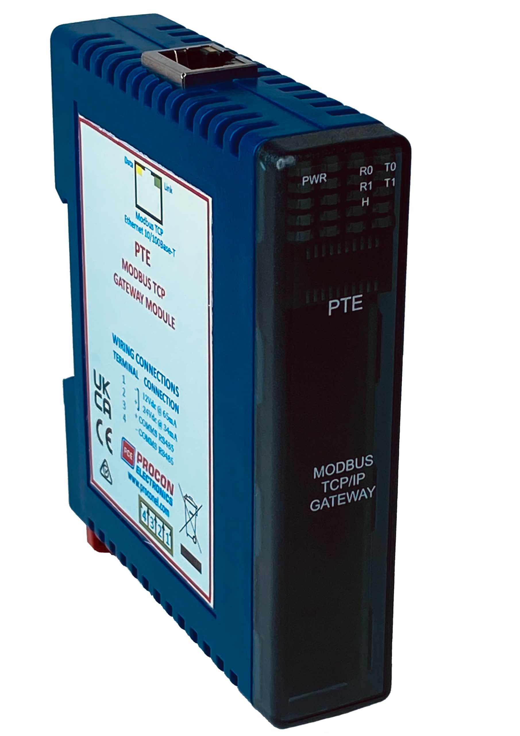
PT-E Modbus TCP Gateway

The PT-E GATEWAY is an Ethernet to serial converter and connects the PROMUX modules to a 10/100 Base-TX Ethernet network.

The PT-E GATEWAY includes a web server which enables access to internal parameters for configuration. This allows configuration of IP address, default gateway IP address and subnet mask. The web server can be accessed by most web browsers.

The PT-E GATEWAY is factory programmed with a default IP address of 169.254.111.111. This address must be changed before the converter is added to an existing network.

The web page address for viewing the setup parameters is http://169.254.111.111/index.htm The web page address for configuring the converter is http://169.254.111.111/ip.htm

The master device which is polling the modules must be configured with the IP address of the PT-E GATEWAY and with the modbus ID of the PROMUX modules. As each PROMUX communications bus is separate, it is possible to have repeated Modbus ID’s on the PROMUX modules provided they are attached to a different PT-E GATEWAY. The IP address differentiates between the different PROMUX systems. Consequently, many hundreds of PROMUX modules may be added to an Ethernet network.

The PT-E GATEWAY is a Modbus gateway and the client must be configured to use Port 502. This is a reserved port number for Modbus TCP applications and informs the PT-E GATEWAY that it must implement the protocol conversion from Modbus TCP on the Ethernet network to Modbus RTU on the PROMUX serial communications bus.

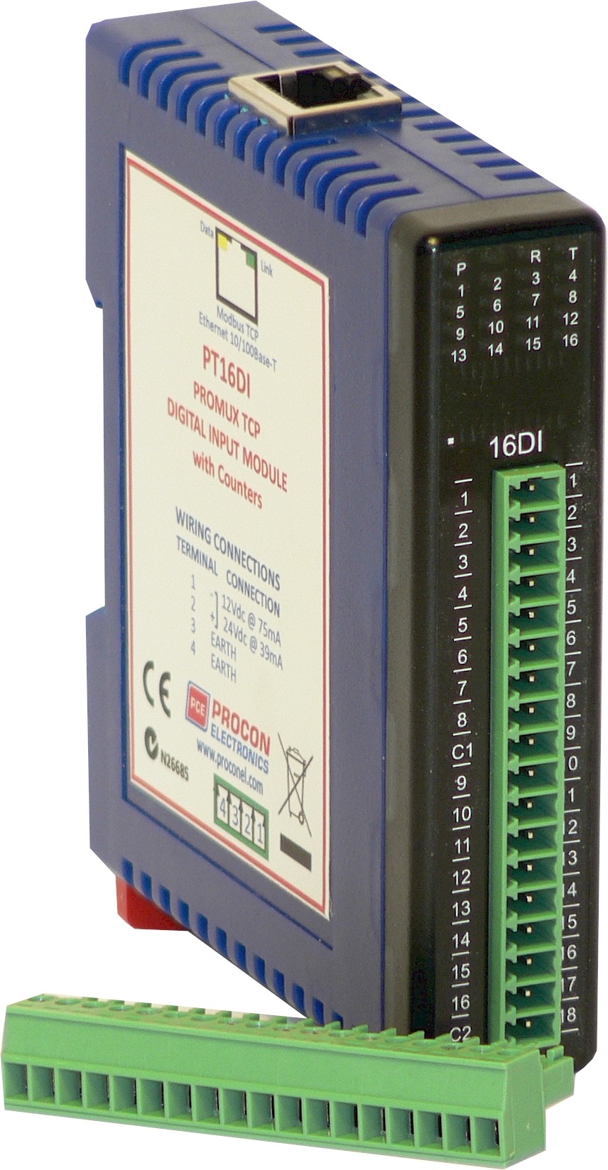
PT16DI – 16 Digital Input Module

The PT16DI module is a 16 channel digital input module. The inputs are isolated from the logic by bi-directional opto-couplers. The inputs are divided into 2 isolated groups of 8 inputs each. This allows for many configurations in which the input module may be used. One such configuration could be where one group is connected as common positive and the second group connected as common negative.

The counters operate in three modes.

In mode 0: All the counters are disabled.

In mode 1: The counters are 32 bit counters allowing a count value from 0 to 4294967295. The count value can be cleared by writing a zero to the associated registers or preset to any other value using the same method.

In mode 2: The inputs are connected as up/down counters. Input 1 will increment counter 1 whilst input 2 decrements counter1. In the same way, inputs 3&4 operate counter 2, inputs 5&6 operate counter 3 and inputs 7&8 operate counter 4,etc.


Note: The count values are not battery backed-up and will be lost if power is turned off.

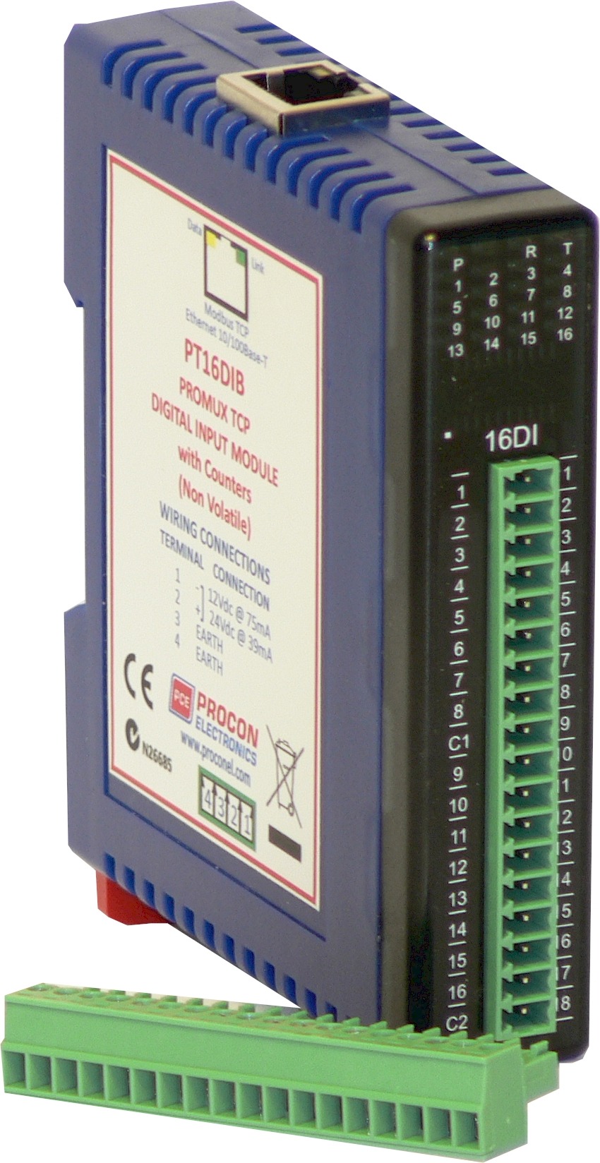
PT16DIB – 16 Digital Input Module with Non-Volatile Counters

The PT16DIB module is a 16 channel digital input module. The inputs are isolated from the logic by bi-directional opto-couplers. The inputs are divided into 2 isolated groups of 8 inputs each. This allows for many configurations in which the input module may be used. One such configuration could be where one group is connected as common positive and the second group connected as common negative.

The counters operate in three modes.

In mode 0: All the counters are disabled.

In mode 1: The counters are 32 bit counters allowing a count value from 0 to 4294967295. The count value can be cleared by writing a zero to the associated registers or preset to any other value using the same method.

In mode 2: The inputs are connected as up/down counters. Input 1 will increment counter 1 whilst input 2 decrements counter1. In the same way, inputs 3&4 operate counter 2, inputs 5&6 operate counter 3 and inputs 7&8 operate counter 4,etc.

When the input filter is configured for > 10ms (Input Filter > 1), then the 16 counters are saved in non-volatile memory and the count value will be saved when the power fails.

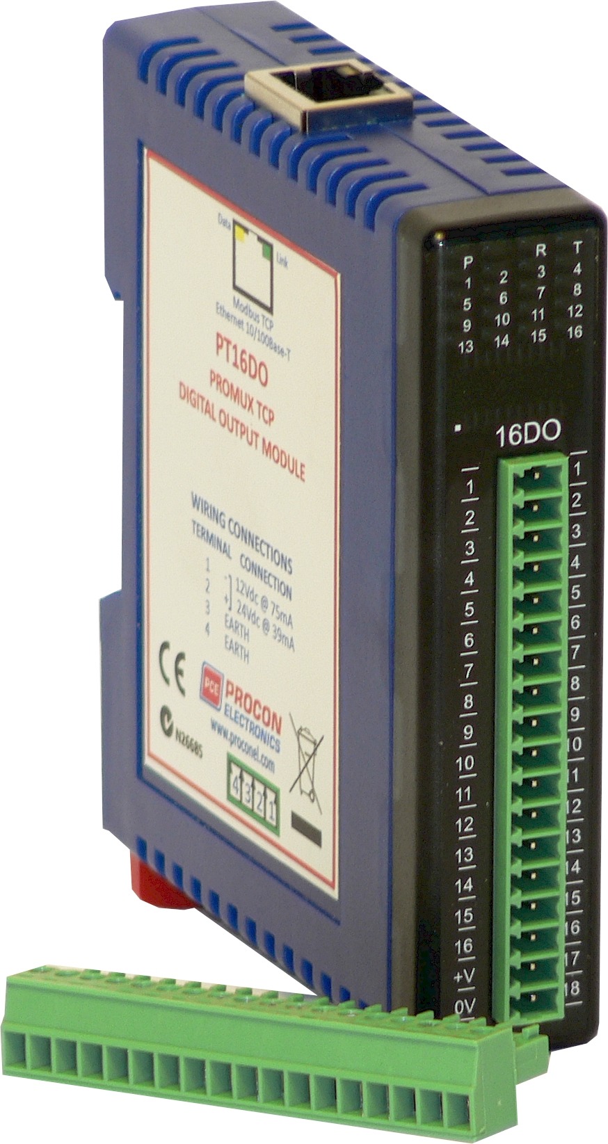
PT16DO – 16 Digital Output Module

This module has 16 open collector (NPN) digital outputs. The outputs may be used to drive lamps or external relays when more drive capability is required. The outputs are isolated from the logic and they share a common negative terminal.

Each output can be individually switched on or off, or all outputs can be set up at the same time by writing a single number to the output register which represents the status of all outputs.

An output watchdog timer can be configured to switch off all the outputs if there has been no communications with the module for up to 255 seconds. A value of 0 seconds will disable this timer and the outputs will remain in the last programmed state.
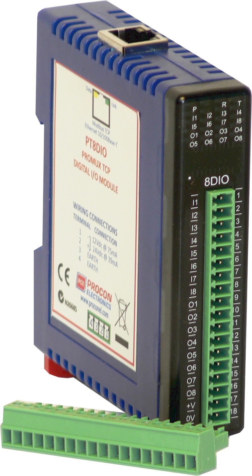
PT8DIO – 8 Digital Input/ Output Module

The PT8DIO module is an 8 channel digital input and 8 channel digital output module.
The inputs are isolated from the logic by bi-directional opto-couplers. The common is connected internally to either the -volts or +volts field power supply terminals using a jumper link which is situated inside the housing.
The inputs have internal counters associated with them. These counters are 32 bit counters allowing a count value from 0 to 4294967295. The count value can be cleared by writing a zero to the associated registers or preset to any other value using the same method.

Note: The count values are not battery backed-up and will be lost if power is turned off.

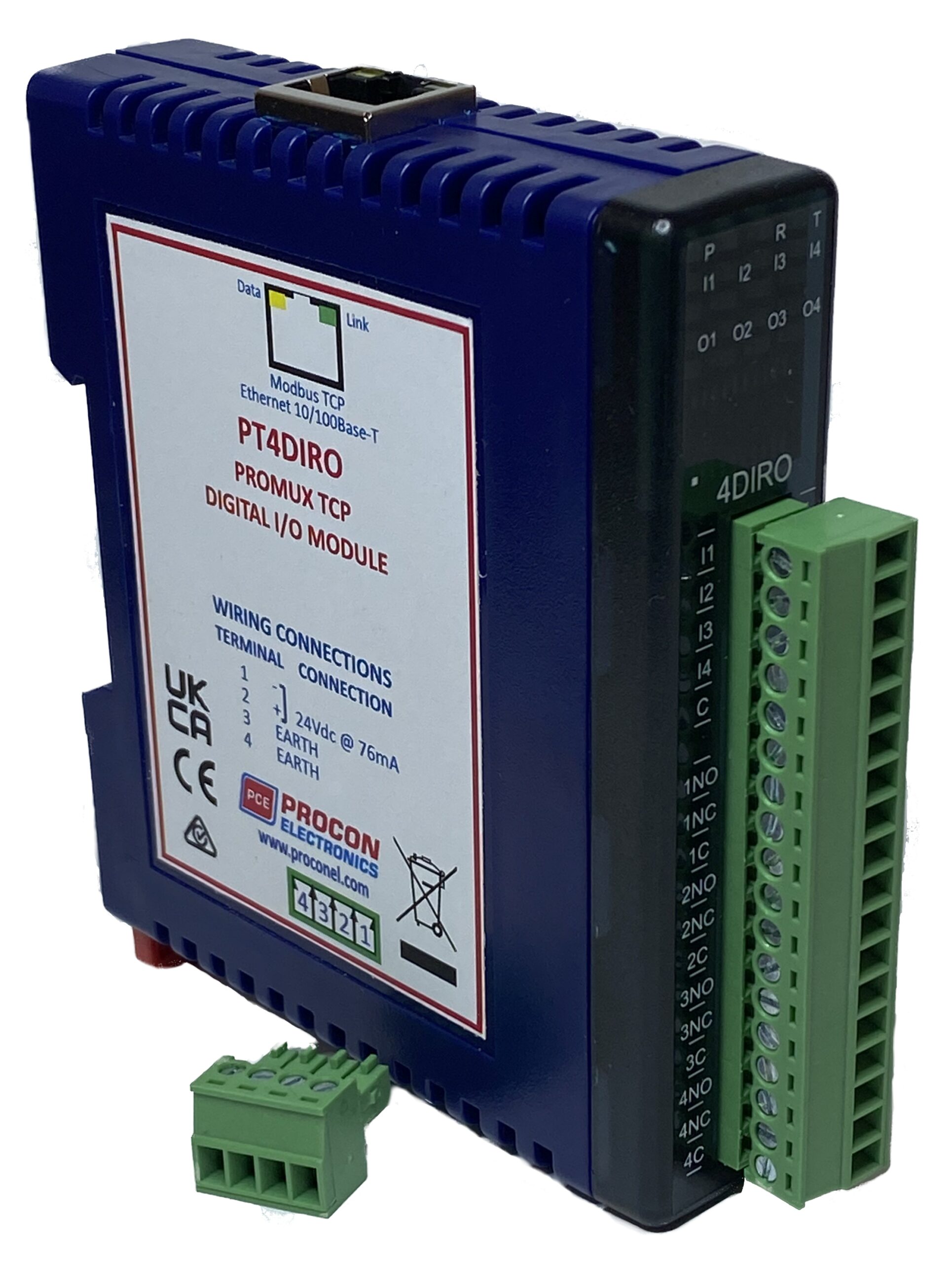
PT4DIRO – 4 Digital Input/ Relay Output Module

The PT4DIRO module is a 4 channel digital input and 4 relay output module.

The inputs are isolated from the logic by bi-directional opto-couplers. The common can be connected to either the -volts or +volts field power supply terminals.

The counters operate in three modes.

In mode 0 all the counters are disabled.

In mode 1 the first eight inputs (1-8) have internal counters associated with them. These counters are 32 bit counters allowing a count value from 0 to 4294967295. The count value can be cleared by writing a zero to the associated registers or preset to any other value using the same method.

In mode 2 the inputs are connected as up/down counters. Input 1 will increment counter 1 whilst input 2 decrements counter1. In the same way, inputs 3&4 operate counter 2.

Note: The count values are not battery backed-up and will be lost if power is turned off.

The format of the registers allows the status of the inputs to be read as either single bits or all at once as a single register on the Modbus network.

The 4 relay outputs provide normally open and normally closed contacts. The outputs may be used to drive lamps or external relays when more drive capability is required. The outputs are isolated from the logic.

When used as a slave module, the outputs are written to by the Modbus master device such as a PC or PLC. Each output can be individually switched on or off, or all outputs can be set up at the same time by writing a single number to the output register which represents the status of all outputs.

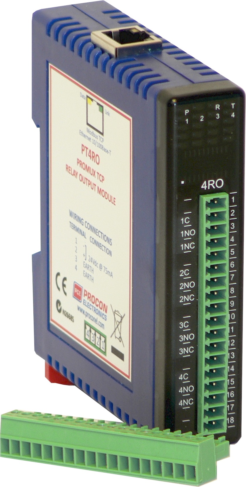
PT4RO – 4 Relay Output Module

The PT4RO module has 4 normally open/ normally closed relay outputs. These modules may be used when a higher drive capability is required, or when isolation between outputs are required.

Each output can be individually switched on or off, or all outputs can be set up at the same time by writing a single number to the output register which represents the status of all outputs.

An output watchdog timer can be configured to switch off all the outputs if there has been no communications with the module for up to 255 seconds. A value of 0 seconds will disable this timer and the outputs will remain in the last programmed state.